Subscribe

RSS Feed (xml)

Powered By

Skin Design:
Free Blogger Skins

Powered by Blogger

Network Security Map Network Protocol Map
Showing posts with label Wi-Fi. Show all posts

Monday, June 16, 2008

Wireless and Cellular Communication by William C.Y. Lee

Publisher: McGraw-Hill Professional
Number Of Pages: 821
Publication Date: 2005-10-22
Sales Rank: 178562
ISBN / ASIN: 0071436863
EAN: 9780071436861
pass: gigapedia.org
Binding: Hardcover
Manufacturer: McGraw-Hill Professional
Studio: McGraw-Hill Professional
Average Rating: 4


The #1 book on wireless communications has been completely updated

World recognized wireless authority William Lee delivers all new in-depth engineering coverage for data sevices, Wi-Fi, 3G, and much more, just in time for the rebounding wireless industry.

Includes specifications for all major wireless systems, including cdmaOne

link for free download: mihd.net

Good book for newbie at Mobile and Cellular Telecommunication. It'sRecommended.

Undergoing MyBlogLog Verification


Read more!

Sunday, June 15, 2008

Public Broadcast Cart

  • Public Broadcast Cart
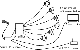
  • is a shopping cart outfitted with a dynamic microphone, a mixer, an amplifier, six speakers, a miniFM transmitter and a laptop with a wireless card. The audio captured by the microphone on the cart is fed through the mixer to three different broadcast sources. The mixer simultaneiously feeds the audio:

    * to the amplifier that powers the six speakers mounted on the cart

    * to an FM transmitter transmitting to an FM frequency

    * to the laptop that sends the audio to an online server that will stream the live broadcast, such as the thing.net's server - http://radio.thing.net

    The Public Broadcast Cart is designed to enable any pedestrian to become an active producer of a radio broadcast. The cart reverses the usual role of the public from audience to producer of a radio broadcast and online content. View original proposal

    As the government and the FCC seek to hand over our media resources to the wealthiest corporate media entities looking to monopolize the media from print to radio to television, it is upto the independent producers to subvert big money domination of our culture.

    The Broadcast Cart was funded by the Franklin Furnace's Future of the Present Fund and technical assistance was given by Jan McLaughlin, Greg Gong, Dana Speigel and Darrel O'Pry. The broadcast has been supported by thing.net, Ars Electronica, Exit Art, Tesla Radio. I would like to give special thanks to Martha Wilson and Wolfgang Staehle for their work as artists, independent producers and supporters of artists, and thanks to Brooke Singer, Yuri Gitman, and Dana Spiegel the producers of the public net art event Wireless Park Lab Days, September 19th and 20th, 2003, when the Public Broadcast Cart was first presented.

    Build Your Own Radio Cart

    Use a simple dynamic microphone plugged into a simple audio mixer that allows multiple output for the audio. The Public Broadcast Cart uses an old, incredibly sturdy and handy SHURE mixer donated by Jan McLaughlin. The closest version available on the SHURE site is the FP23 Microphone Preamplifer

    Ramsey Electronics offers a great selection of affordable small transmitters from a $35 AM Radio Transmitter Kit to $300 Factory Assembled and Tested Digital FM Stereo Transmitter. The Public Broadcast Cart uses Ramsey's Professional Synthesized FM Stereo Transmitter Kit, it's an excellent learning experience to assemble your own transmitter.

    If you have a wifi equiped laptop and an open wifi node available all you need is Internet radio broadcasting software. Rogue Amoeba's Nicecast allows you to turn your own computer into the broadcasting server. A better idea is to use Nicecast to stream the audio to a server designed to handle online broadcasting.

    For immediate area audio amplification, just about anything that can recieve audio from the mixer and output it through speakers could be used, even a boom box. The Public Broadcast Cart uses the Samson SERVO 120A 120-Watt Power Amplifier that powers car speakers that have been mounted onto goose neck microphone extensions

    The Public Broadcast Cart has used a few different power sources from as poor as car batteries to as a stable power supply as the Galaxy Far Outlet Model 300S, which Gotham Sound rents for a very low price.

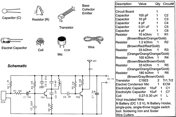
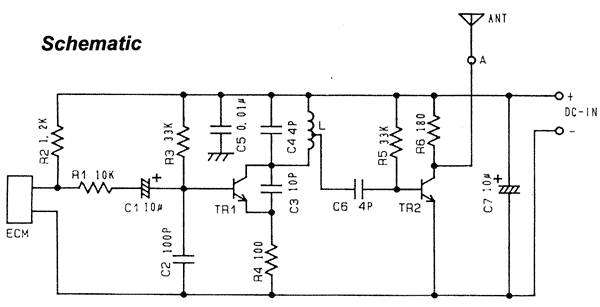
    Tetsuo Kogawa's 1 Watt Transmitter Schematic:


    Read more!

    Thursday, May 29, 2008

    Exploring GNU Radio - Applications

    In addition to the examples discussed above, GNU Radio comes with a complete HDTV transmitter and receiver, a spectrum analyzer, an oscilloscope, concurrent multichannel receiver and an ever-growing collection of modulators and demodulators.
    Projects under investigation or in progress include:
    A TiVo equivalent for radio, capable of recording multiple stations simultaneously.
    Time Division Multiple Access (TDMA) waveforms.
    A passive radar system that takes advantage of broadcast TV for its signal source. For those of you with old TVs hooked to antennas, think about the flutter you see when airplanes fly over.
    Radio astronomy.
    TETRA transceiver.
    Digital Radio Mundial (DRM).
    Software GPS.
    Distributed sensor networks.
    Distributed measurement of spectrum utilization.
    Amateur radio transceivers.
    Ad hoc mesh networks.
    RFID detector/reader.
    Multiple input multiple output (MIMO) processing.


    Read more!

    Exploring GNU Radio by Eric Blossom - What Goes in the FPGA?

    An FPGA is like a small, massively parallel computer that you design to do exactly what you want. Programming the FPGA takes a bit of skill, and mistakes can fry the board permanently. That said, we provide a standard configuration that is useful for a wide variety of applications.
    Using a good USB host controller, the USRP can sustain 32 MB/sec across the USB. The USB is half-duplex. Based on your needs, you partition the 32 MB/sec between the transmit and the receive directions. In the receive direction, the standard configuration allows you to select the part or parts of the digitized spectrum you're interested in, translate them to baseband and decimate as required. This is exactly equivalent to what's happening in the RF front end, only now we're doing it on digitized samples. The block of code that performs this function is called a digital down converter (Figure 3, “Digital Down Converter Block Diagram”). One advantage of performing this function in the digital domain is we can change the center frequency instantaneously, which is handy for frequency hopping spread spectrum systems.


    Figure 3. Digital Down Converter Block Diagram

    In the transmit direction, the exact inverse is performed. The FPGA contains multiple instances of the digital up and down converters. These instances can be connected to the same or different ADCs, depending on your needs. We don't have room here to cover all the theory behind them; see the GNU Radio Wiki for more information.


    Read more!

    Exploring GNU Radio by Eric Blossom - GUI, Hardware requirements and USR Peripheral

    Graphical interfaces for GNU Radio applications are built in Python. Interfaces may be built using any toolkit you can access from Python; we recommend wxPython to maximize cross-platform portability. GNU Radio provides blocks that use interprocess communication to transfer chunks of data from the real-time C++ flow graph to Python-land.

    GNU Radio is reasonably hardware-independent. Today's commodity multi-gigahertz, super-scalar CPUs with single-cycle floating-point units mean that serious digital signal processing is possible on the desktop. A 3 GHz Pentium or Athlon can evaluate 3 billion floating-point FIR taps/s. We now can build, virtually all in software, communication systems unthinkable only a few years ago.
    Your computational requirements depend on what you're trying to do, but generally speaking, a 1 or 2 GHz machine with at least 256 MB of RAM should suffice. You also need some way to connect the analog world to your computer. Low-cost options include built-in sound cards and audiophile quality 96 kHz, 24-bit, add-in cards. With either of these options, you are limited to processing relatively narrow band signals and need to use some kind of narrow-band RF front end.
    Another possible solution is an off-the-shelf, high-speed PCI analog-to-digital board. These are available in the 20M sample/sec range, but they are expensive, about the cost of a complete PC. For these high-speed boards, cable modem tuners make reasonable RF front ends.
    Finding none of these alternatives completely satisfactory, we designed the Universal Software Radio Peripheral, or USRP for short.

    Our preferred hardware solution is the Universal Software Radio Peripheral (USRP). Figure 2, “Universal Software Radio Peripheral” shows the block diagram of the USRP. The brainchild of Matt Ettus, the USRP is an extremely flexible USB device that connects your PC to the RF world. The USRP consists of a small motherboard containing up to four 12-bit 64M sample/sec ADCs, four 14-bit, 128M sample/sec DACs, a million gate-field programmable gate array (FPGA) and a programmable USB 2.0 controller. Each fully populated USRP motherboard supports four daughterboards, two for receive and two for transmit. RF front ends are implemented on the daughterboards. A variety of daughterboards is available to handle different frequency bands. For amateur radio use, low-power daughterboards are available that receive and transmit in the 440 MHz band and the 1.24 GHz band. A receive-only daughterboard based on a cable modem tuner is available that covers the range from 50 MHz to 800 MHz. Daughterboards are designed to be easy to prototype by hand in order to facilitate experimentation.


    Figure 2. Universal Software Radio Peripheral

    The flexibility of the USRP comes from the two programmable components on the board and their interaction with the host-side library. To get a feel for the USRP, let's look at its boot sequence. The USRP itself contains no ROM-based firmware, merely a few bytes that specify the vendor ID (VID), product ID (PID) and revision. When the USRP is plugged in to the USB for the first time, the host-side library sees an unconfigured USRP. It can tell it's unconfigured by reading the VID, PID and revision. The first thing the library code does is download the 8051 code that defines the behavior of the USB peripheral controller. When this code boots, the USRP simulates a USB disconnect and reconnect. When it reconnects, the host sees a different device: the VID, PID and revision are different. The firmware now running defines the USB endpoints, interfaces and command handlers. One of the commands the USB controller now understands is load the FPGA. The library code, after seeing the USRP reconnect as the new device, goes to the next stage of the boot process and downloads the FPGA configuration bitstream.
    FPGAs are generic hardware chips whose behavior is determined by the configuration bitstream that's loaded into them. You can think of the bitstream as object code. The bitstream is the output of compiling a high-level description of the design. In our case, the design is coded in the Verilog hardware description language. This is source code and, like the rest of the code in GNU Radio, is licensed under the GNU General Public License.


    Read more!

    Exploring GNU Radio by Eric Blossom - A Complete FM Receiver

    Example 2 shows a somewhat simplified but complete broadcast FM receiver. It includes control of the RF front end and all required signal processing. This example uses an RF front end built from a cable modem tuner and a 20M sample/sec analog-to-digital converter.

    Example 2. Broadcast FM Receiver#!/usr/bin/env python
    from gnuradio import gr
    from gnuradio import audio
    from gnuradio import mc4020
    import sys
    def high_speed_adc (fg, input_rate):
    # return gr.file_source (gr.sizeof_short, "dummy.dat", False)
    return mc4020.source (input_rate, mc4020.MCC_CH3_EN mc4020.MCC_ALL_1V)
    #
    # return a gr.flow_graph
    #
    def build_graph (freq1, freq2):
    input_rate = 20e6
    cfir_decimation = 125
    audio_decimation = 5
    quad_rate = input_rate / cfir_decimation
    audio_rate = quad_rate / audio_decimation
    fg = gr.flow_graph ()

    # use high speed ADC as input source
    src = high_speed_adc (fg, input_rate)

    # compute FIR filter taps for channel selection
    channel_coeffs = \
    gr.firdes.low_pass (1.0, # gain
    input_rate, # sampling rate
    250e3, # low pass cutoff freq
    8*100e3, # width of trans. band
    gr.firdes.WIN_HAMMING)
    # input: short; output: complex
    chan_filter1 = \
    gr.freq_xlating_fir_filter_scf (cfir_decimation,
    channel_coeffs,
    freq1, # 1st station freq
    input_rate)

    (head1, tail1) = build_pipeline (fg, quad_rate, audio_decimation)

    # sound card as final sink
    audio_sink = audio.sink (int (audio_rate))
    # now wire it all together
    fg.connect (src, chan_filter1)
    fg.connect (chan_filter1, head1)
    fg.connect (tail1, (audio_sink, 0))
    return fg
    def build_pipeline (fg, quad_rate, audio_decimation):
    '''Given a flow_graph, fg, construct a pipeline
    for demodulating a broadcast FM signal. The
    input is the downconverted complex baseband
    signal. The output is the demodulated audio.
    build_pipeline returns a two element tuple
    containing the input and output endpoints.
    '''
    fm_demod_gain = 2200.0/32768.0
    audio_rate = quad_rate / audio_decimation
    volume = 1.0
    # input: complex; output: float
    fm_demod = gr.quadrature_demod_cf (volume*fm_demod_gain)
    # compute FIR filter taps for audio filter
    width_of_transition_band = audio_rate / 32
    audio_coeffs = gr.firdes.low_pass (1.0, # gain
    quad_rate, # sampling rate
    audio_rate/2 - width_of_transition_band,
    width_of_transition_band,
    gr.firdes.WIN_HAMMING)
    # input: float; output: float
    audio_filter = gr.fir_filter_fff (audio_decimation, audio_coeffs)
    fg.connect (fm_demod, audio_filter)
    return ((fm_demod, 0), (audio_filter, 0))

    def main (args):
    nargs = len (args)
    if nargs == 1:
    # get station frequency from command line
    freq1 = float (args[0]) * 1e6
    else:
    sys.stderr.write ('usage: fm_demod freq\n')
    sys.exit (1)
    # connect to RF front end
    rf_front_end = gr.microtune_4937_eval_board ()
    if not rf_front_end.board_present_p ():
    raise IOError, 'RF front end not found'
    # set front end gain
    rf_front_end.set_AGC (300)
    # determine the front end's "Intermediate Frequency"
    IF_freq = rf_front_end.get_output_freq () # 5.75e6
    # Tell the front end to tune to freq1.
    # I.e., freq1 is translated down to the IF frequency
    rf_front_end.set_RF_freq (freq1)
    # build the flow graph
    fg = build_graph (IF_freq, None)

    fg.start () # fork thread(s) and return
    raw_input ('Press Enter to quit: ')
    fg.stop ()
    if __name__ == '__main__':
    main (sys.argv[1:])
    Like the Hello World example, we build a graph, connect the blocks together and start it. In this case, our source, mc4020.source, is an interface to the Measurement Computing PCI-DAS 4020/12 high-speed ADC. We follow it with gr.freq_xlating_fir_filter_scf, a finite impulse response (FIR) filter that selects the FM station we're looking for and translates it to baseband (0Hz, DC). With the 20M sample/sec converter and cable modem tuner, we're really grabbing something in the neighborhood of a 6 MHz chunk of the spectrum. This single chunk may contain ten or more FM stations, and gr.freq_xlating_fir_filter_scf allows us to select the one we want.
    In this case, we select the one at the exact center of the IF of the RF front end (5.75 MHz). The output of gr.freq_xlating_fir_filter_scf is a stream of complex samples at 160,000 samples/second. We feed the complex baseband signal into gr.quadrature_demod_cf, the block that does the actual FM demodulation.
    gr.quadrature_demod_cf works by subtracting the angle of each adjacent complex sample, effectively differentiating the frequency. The output of gr.quadrature_demod_cf contains the left-plus-right FM mono audio signal, the stereo pilot tone at 19kHz, the left-minus-right stereo information centered at 38kHz and any other sub-carriers above that. For this simplified receiver, we finish off by low pass filtering and decimating the stream, keeping only the left-plus-right audio information, and send that to the sound card at 32,000 samples/sec.
    For a more indepth look at how the FM receiver works, please see "Listening to FM, Step by Step."


    Read more!

    Exploring GNU Radio by Eric Blossom - Block Diagram


    Figure 1, “Typical software radio block diagram” shows a typical block diagram for a software radio. To understand the software part of the radio, we first need to understand a bit about the associated hardware. Examining the receive path in the figure, we see an antenna, a mysterious RF front end, an analog-to-digital converter (ADC) and a bunch of code. The analog-to-digital converter is the bridge between the physical world of continuous analog signals and the world of discrete digital samples manipulated by software.


    Figure 1. Typical software radio block diagram
    ADCs have two primary characteristics, sampling rate and dynamic range. Sampling rate is the number of times per second that the ADC measures the analog signal. Dynamic range refers to the difference between the smallest and largest signal that can be distinguished; it's a function of the number of bits in the ADC's digital output and the design of the converter. For example, an 8-bit converter at most can represent 256 (28) signal levels, while a 16-bit converter represents up to 65,536 levels. Generally speaking, device physics and cost impose trade-offs between the sample rate and dynamic range.
    Before we dive into the software, we need to talk about a bit of theory. In 1927, a Swedish-born physicist and electrical engineer named Harry Nyquist determined that to avoid aliasing when converting from analog to digital, the ADC sampling frequency must be at least twice the bandwidth of the signal of interest. Aliasing is what makes the wagon wheels look like they're going backward in the old westerns: the sampling rate of the movie camera is not fast enough to represent the position of the spokes unambiguously.
    Assuming we're dealing with low pass signals - signals where the bandwidth of interest goes from 0 to fMAX, the Nyquist criterion states that our sampling frequency needs to be at least 2 * fMAX. But if our ADC runs at 20 MHz, how can we listen to broadcast FM radio at 92.1 MHz? The answer is the RF front end. The receive RF front end translates a range of frequencies appearing at its input to a lower range at its output. For example, we could imagine an RF front end that translated the signals occurring in the 90 - 100 MHz range down to the 0 - 10 MHz range.
    Mostly, we can treat the RF front end as a black box with a single control, the center of the input range that's to be translated. As a concrete example, a cable modem tuner module that we've employed successfully has the following characteristics. It translates a 6 MHz chunk of the spectrum centered between about 50 MHz and 800 MHz down to an output range centered at 5.75 MHz. The center frequency of the output range is called the intermediate frequency, or IF.
    In the simplest-thing-that-possibly-could-work category, the RF front end may be eliminated altogether. One GNU Radio experimenter has listened to AM and shortwave broadcasts by connecting a 100-foot piece of wire directly to his 20M sample/sec ADC.
    On to the Software
    GNU Radio provides a library of signal processing blocks and the glue to tie it all together. The programmer builds a radio by creating a graph (as in graph theory) where the vertices are signal processing blocks and the edges represent the data flow between them. The signal processing blocks are implemented in C++. Conceptually, blocks process infinite streams of data flowing from their input ports to their output ports. Blocks' attributes include the number of input and output ports they have as well as the type of data that flows through each. The most frequently used types are short, float and complex.
    Some blocks have only output ports or input ports. These serve as data sources and sinks in the graph. There are sources that read from a file or ADC, and sinks that write to a file, digital-to-analog converter (DAC) or graphical display. About 100 blocks come with GNU Radio. Writing new blocks is not difficult.
    Graphs are constructed and run in Python. Example 1 is the "Hello World" of GNU Radio. It generates two sine waves and outputs them to the sound card, one on the left channel, one on the right.

    Example 1. Dial Tone Output#!/usr/bin/env python
    from gnuradio import gr
    from gnuradio import audio
    def build_graph ():
    sampling_freq = 48000
    ampl = 0.1
    fg = gr.flow_graph ()
    src0 = gr.sig_source_f (sampling_freq, gr.GR_SIN_WAVE, 350, ampl)
    src1 = gr.sig_source_f (sampling_freq, gr.GR_SIN_WAVE, 440, ampl)
    dst = audio.sink (sampling_freq)
    fg.connect ((src0, 0), (dst, 0))
    fg.connect ((src1, 0), (dst, 1))
    return fg
    if __name__ == '__main__':
    fg = build_graph ()
    fg.start ()
    raw_input ('Press Enter to quit: ')
    fg.stop ()
    We start by creating a flow graph to hold the blocks and connections between them. The two sine waves are generated by the gr.sig_source_f calls. The f suffix indicates that the source produces floats. One sine wave is at 350 Hz, and the other is at 440 Hz. Together, they sound like the US dial tone.
    audio.sink is a sink that writes its input to the sound card. It takes one or more streams of floats in the range -1 to +1 as its input. We connect the three blocks together using the connect method of the flow graph.
    connect takes two parameters, the source endpoint and the destination endpoint, and creates a connection from the source to the destination. An endpoint has two components: a signal processing block and a port number. The port number specifies which input or output port of the specified block is to be connected. In the most general form, an endpoint is represented as a python tuple like this: (block, port_number). When port_number is zero, the block may be used alone.
    These two expressions are equivalent:fg.connect ((src1, 0), (dst, 1))
    fg.connect (src1, (dst, 1))
    Once the graph is built, we start it. Calling start forks one or more threads to run the computation described by the graph and returns control immediately to the caller. In this case, we simply wait for any keystroke.


    Read more!

    Exploring GNU Radio by Eric Blossom

    Introduction

    Software radio is the technique of getting code as close to the antenna as possible. It turns radio hardware problems into software problems. The fundamental characteristic of software radio is that software defines the transmitted waveforms, and software demodulates the received waveforms. This is in contrast to most radios in which the processing is done with either analog circuitry or analog circuitry combined with digital chips. GNU Radio is a free software toolkit for building software radios.
    Software radio is a revolution in radio design due to its ability to create radios that change on the fly, creating new choices for users. At the baseline, software radios can do pretty much anything a traditional radio can do. The exciting part is the flexibility that software provides you. Instead of a bunch of fixed function gadgets, in the next few years we'll see a move to universal communication devices. Imagine a device that can morph into a cell phone and get you connectivity using GPRS, 802.11 Wi-Fi, 802.16 WiMax, a satellite hookup or the emerging standard of the day. You could determine your location using GPS, GLONASS or both.
    Perhaps most exciting of all is the potential to build decentralized communication systems. If you look at today's systems, the vast majority are infrastructure-based. Broadcast radio and TV provide a one-way channel, are tightly regulated and the content is controlled by a handful of organizations. Cell phones are a great convenience, but the features your phone supports are determined by the operator's interests, not yours.
    A centralized system limits the rate of innovation. We could take some lessons from the Internet and push the smarts out to the edges. Instead of cell phones being second-class citizens, usable only if infrastructure is in place and limited to the capabilities determined worthwhile by the operator, we could build smarter devices. These user-owned devices would generate the network. They'd create a mesh among themselves, negotiate for backhaul and be free to evolve new solutions, features and applications.


    Read more!
    TCP/IP Quick Guide 3G Wireless Quick Guide (electronic and printed bundle)